THE PINGLER MOD
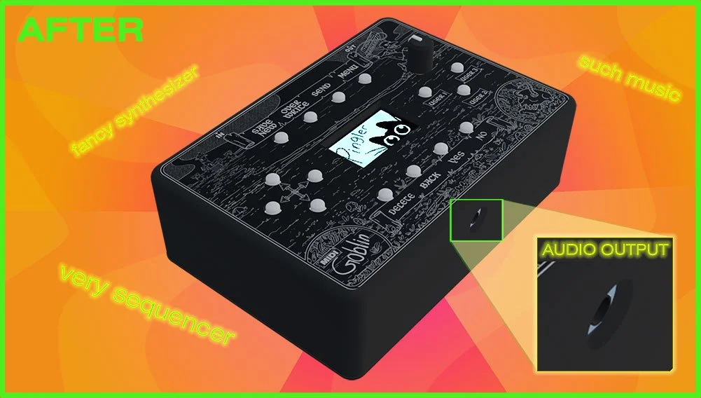
Add audio output and unlock the power of the Pingler synthesizer firmware!
Is this permanent?
The audio module will be soldered to the MIDI Goblin PCB during this tutorial. If you want to remove it, you’ll need to use a solder sucker and some flux. You can switch between the MIDI Goblin and Pingler firmware any time you want though and you don’t need to change the SD Card (the files generated by both firmwares are tiiiny)
Is the soldering hard?
Not really - there are 10 through-hole solder points in total, but a few of them can be tricky if you try to solder from the wrong side of the PCB…if you have no experience, you should practice a bit first..and use helping hands!
What you’ll need:
An original MIDI Goblin....unless you built one yourself using the schematics
A soldering iron
Helping hands to hold the pcb/audio module while you solder (you definitively need these) - tape or sticky tack are also helpful for holding wires in place temporarily.
A white pencil crayon
A drill and drill bits (a step drill bit works best)
Access to a resin 3d printer - or just use an online 3d printing service
A GY-PCM5102 I2S DAC Decoder I2S (they go for about $10-$20 online...shop around but get the right model!)
The newest Pingler firmware
About an hour of time, steady hands, nerves of steal!
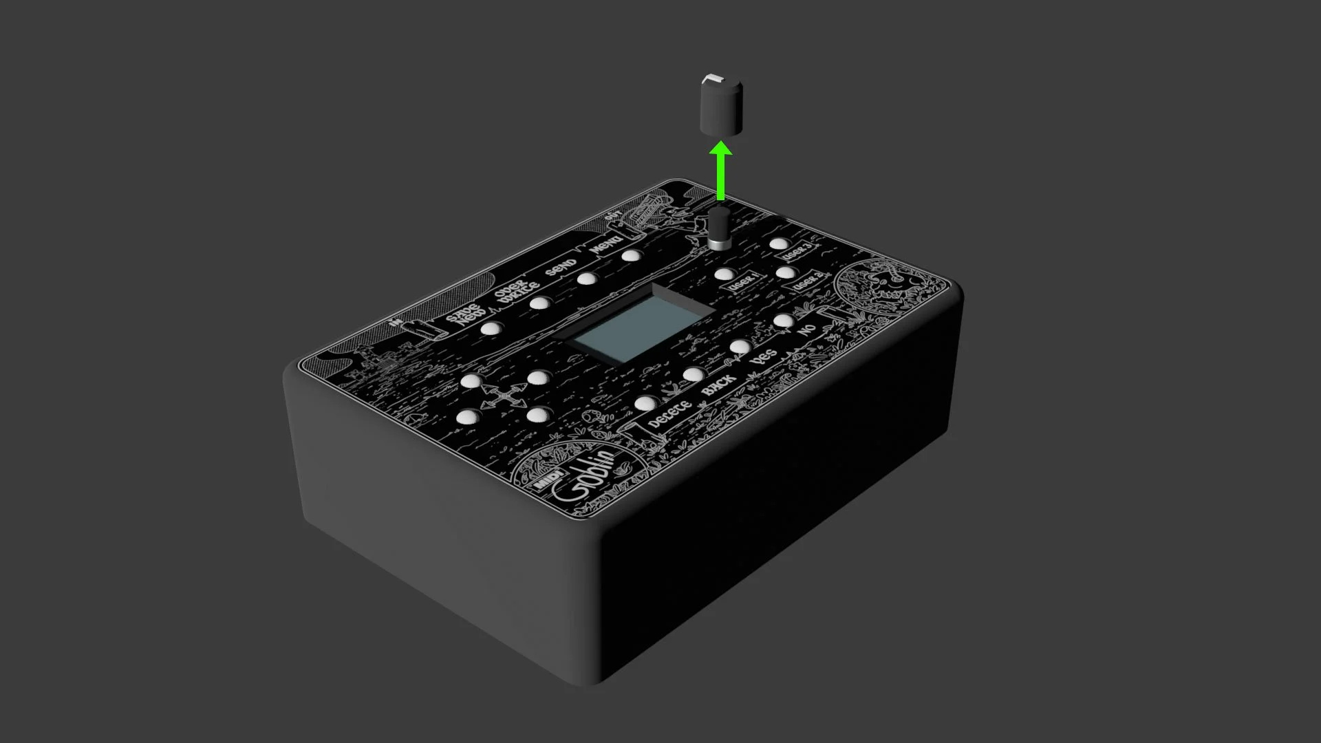
Step 1: take off the encoder knob
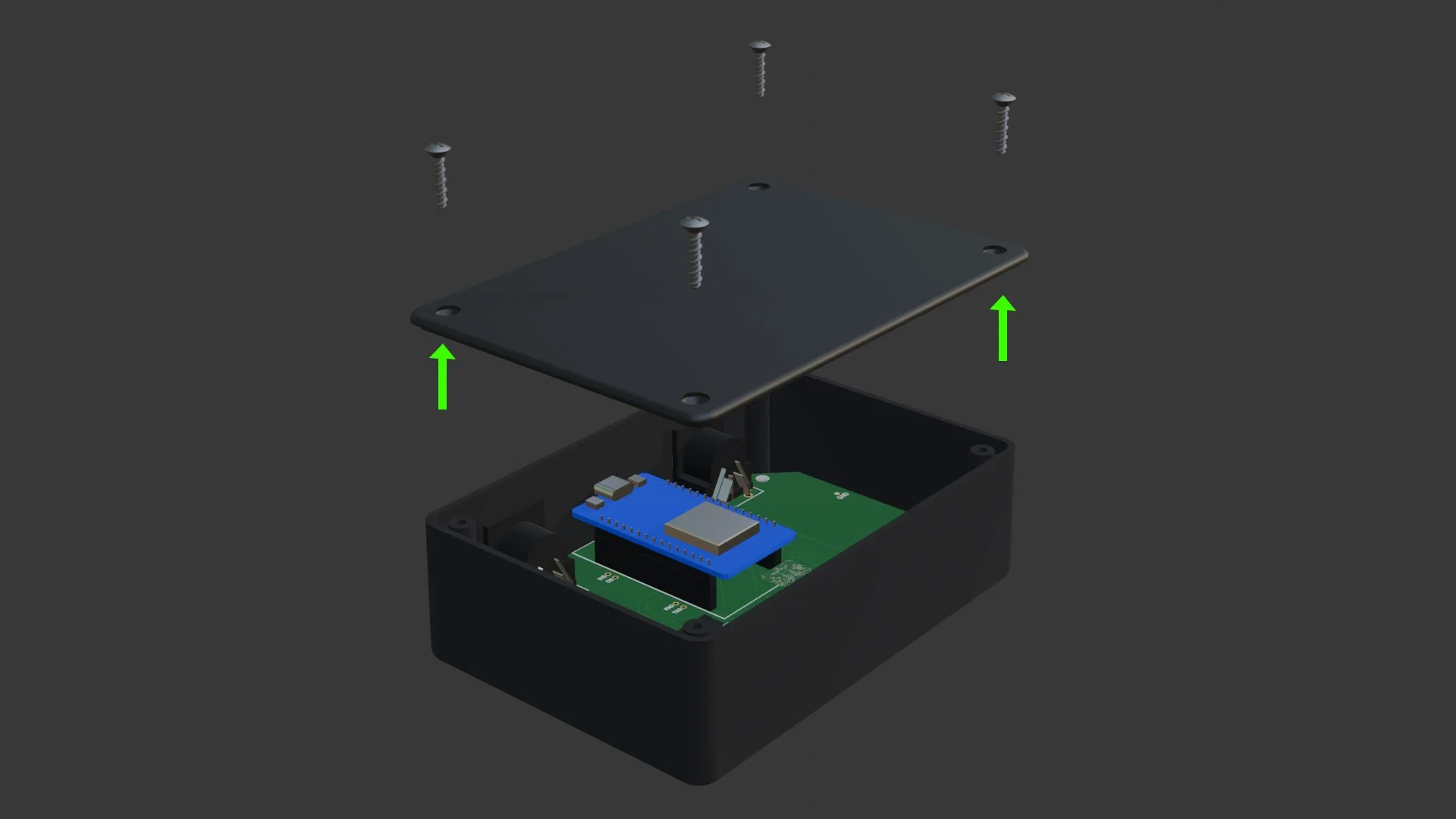
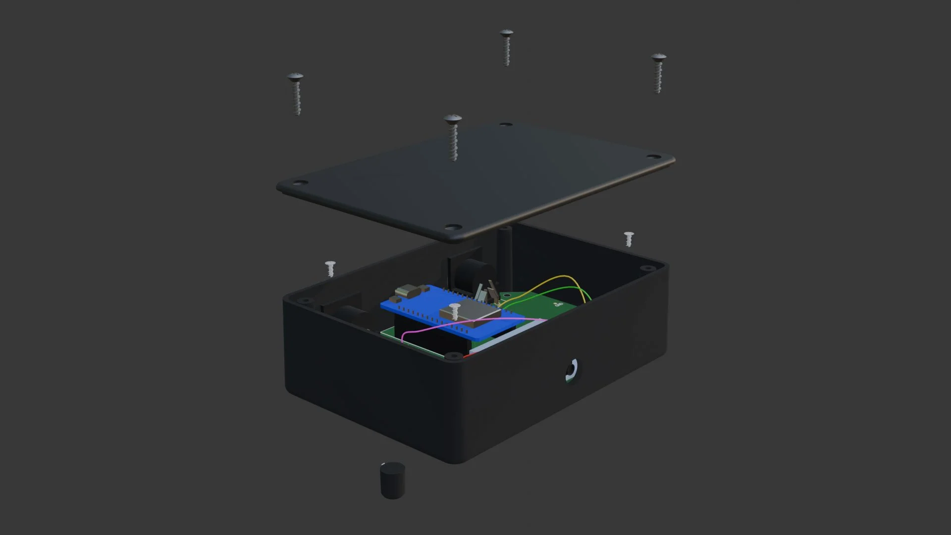
Step 2: remove the bottom plate
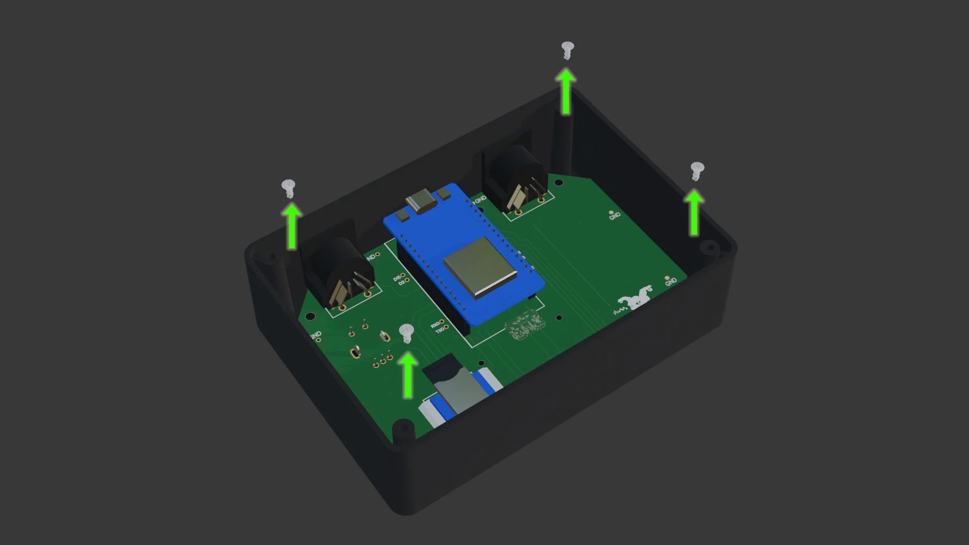
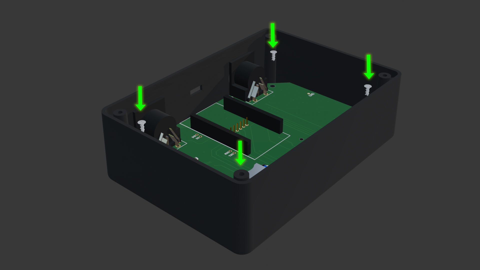
Step 3: remove the PCB screws
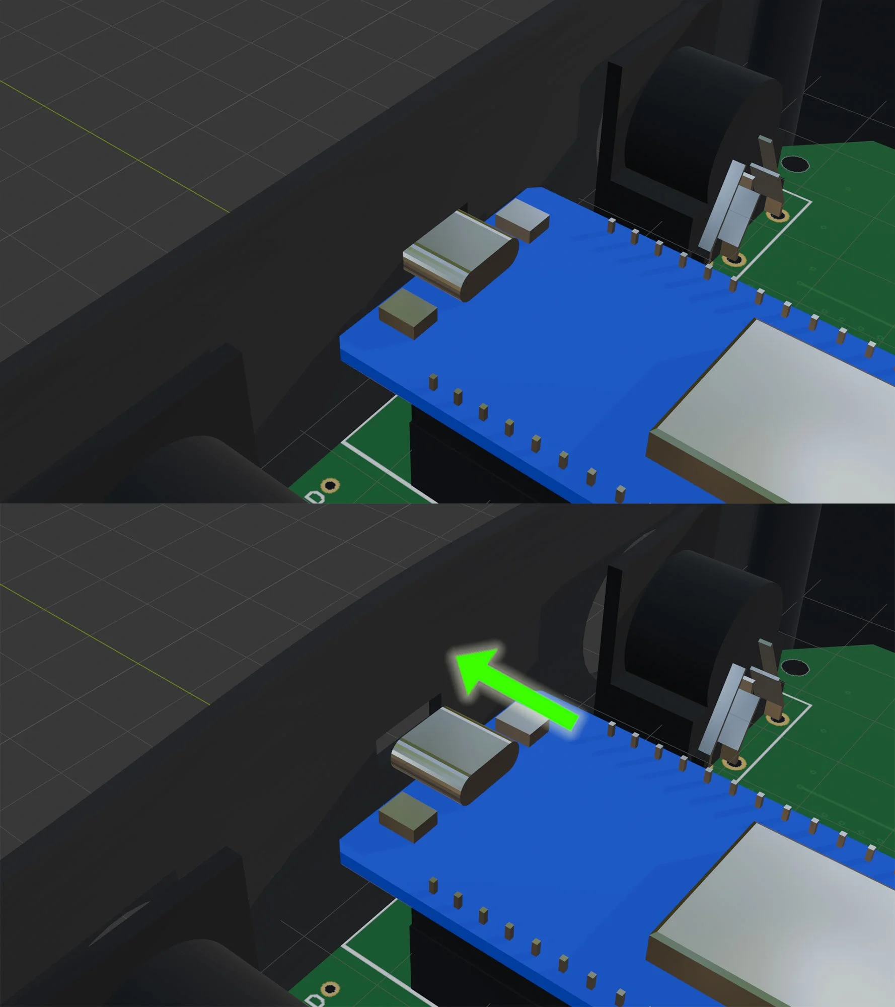
Step 4: release the esp32 by gently prying the enclosure outward a couple millimeters
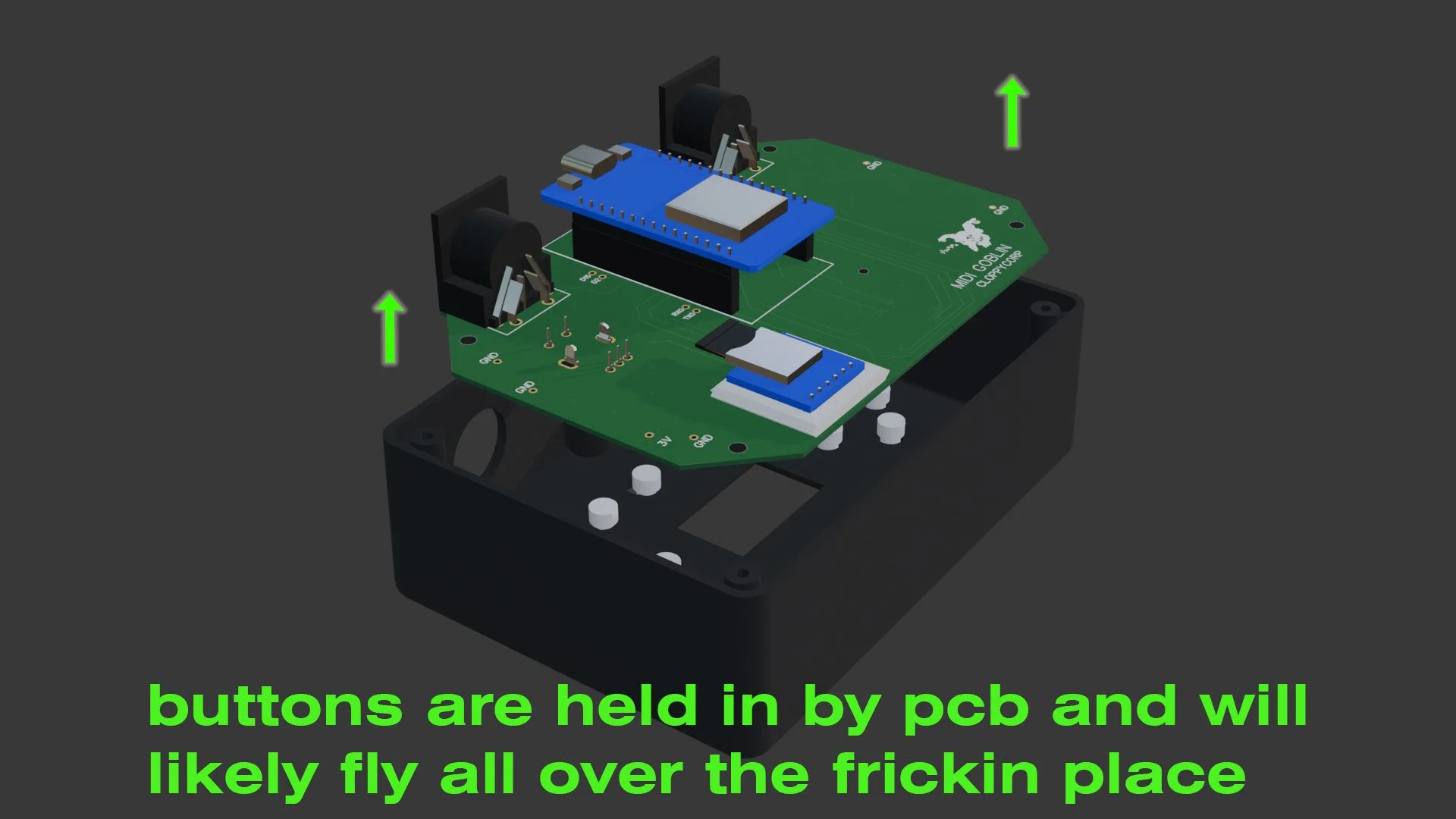
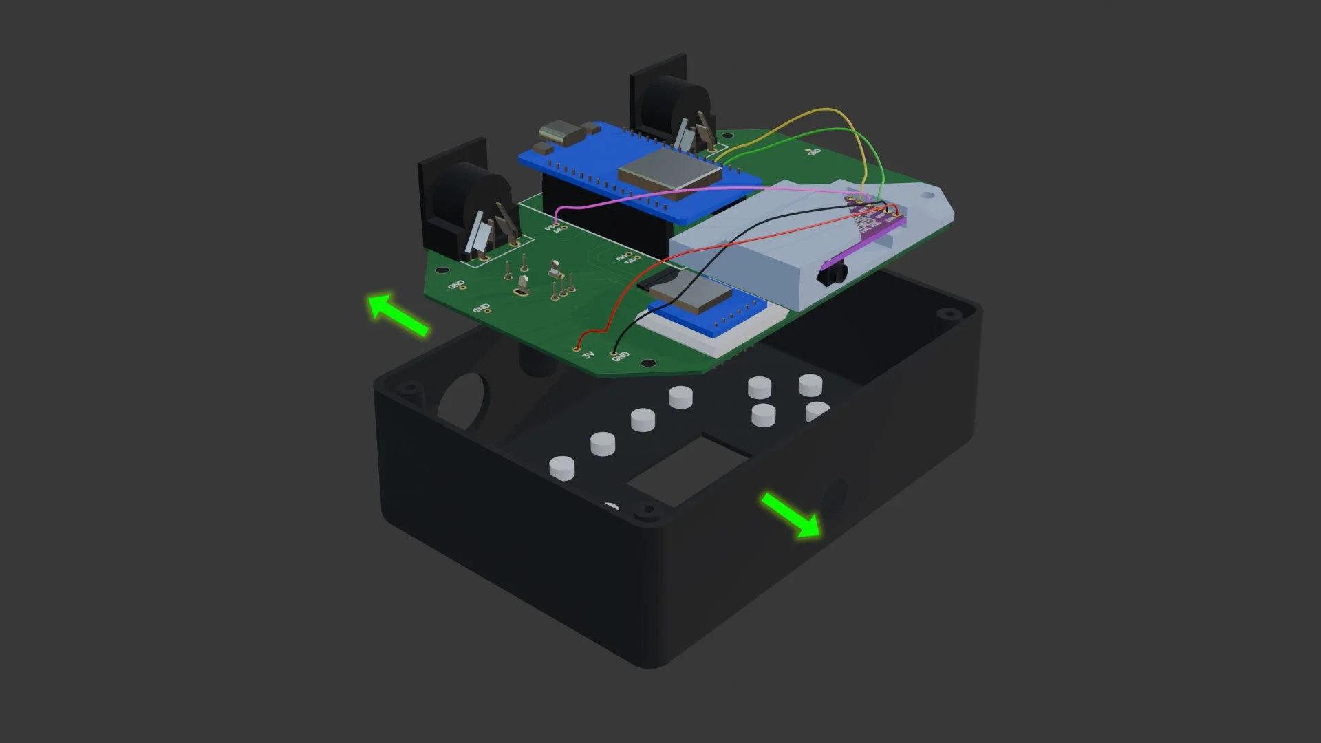
Step 5: remove the electronics and buttons from the MIDI Goblin
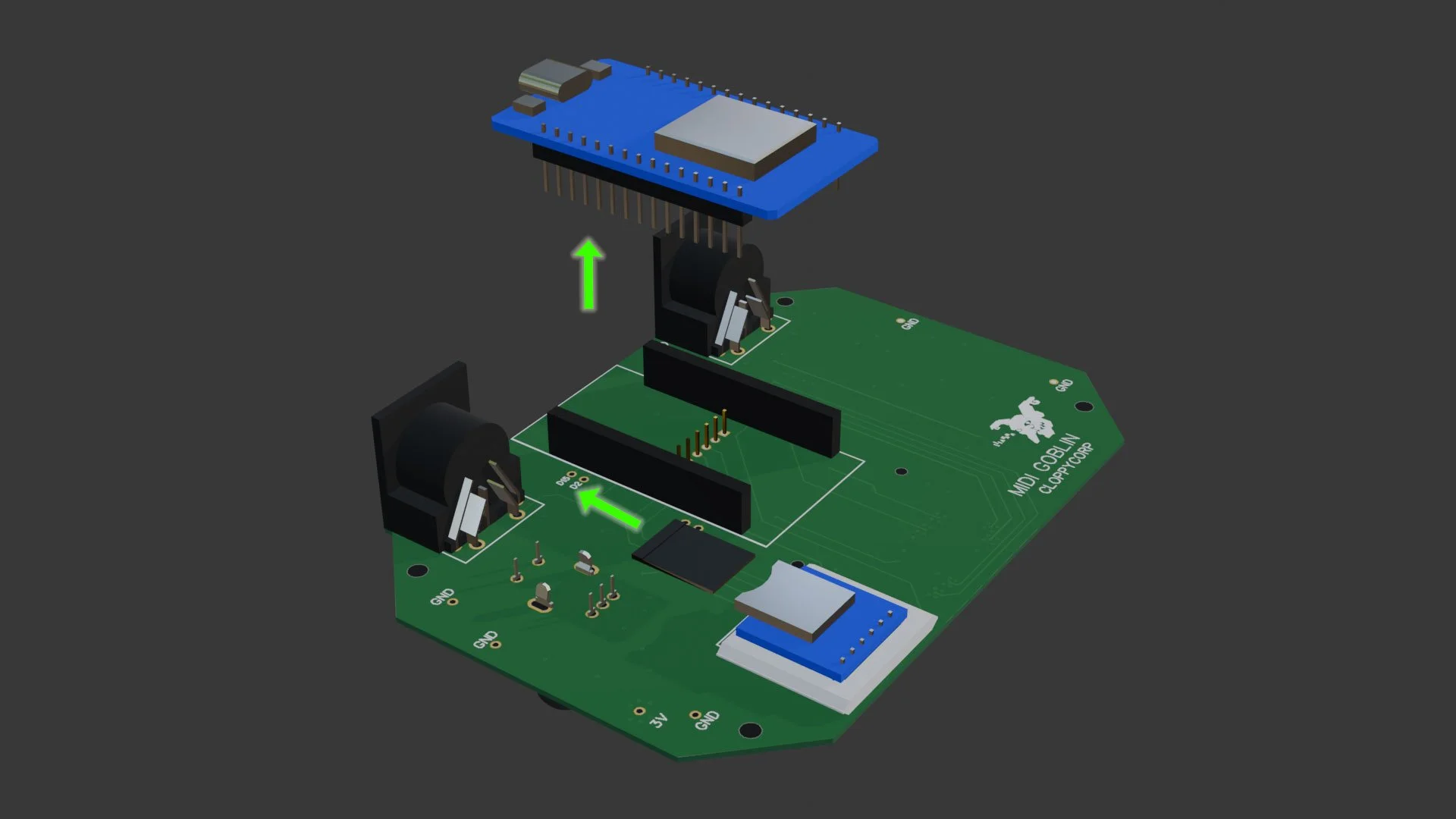
Step 6: remove the esp32 and micro sd card …slowly wiggle the esp32 out of the headers so you don’t stab yourself in the fingernail with one of the pins (I’ve done it before…multiple times)
Step 7: put the pcb back into the enclosure and screw it in place (this might seem weird but its important for getting accurate measurements)
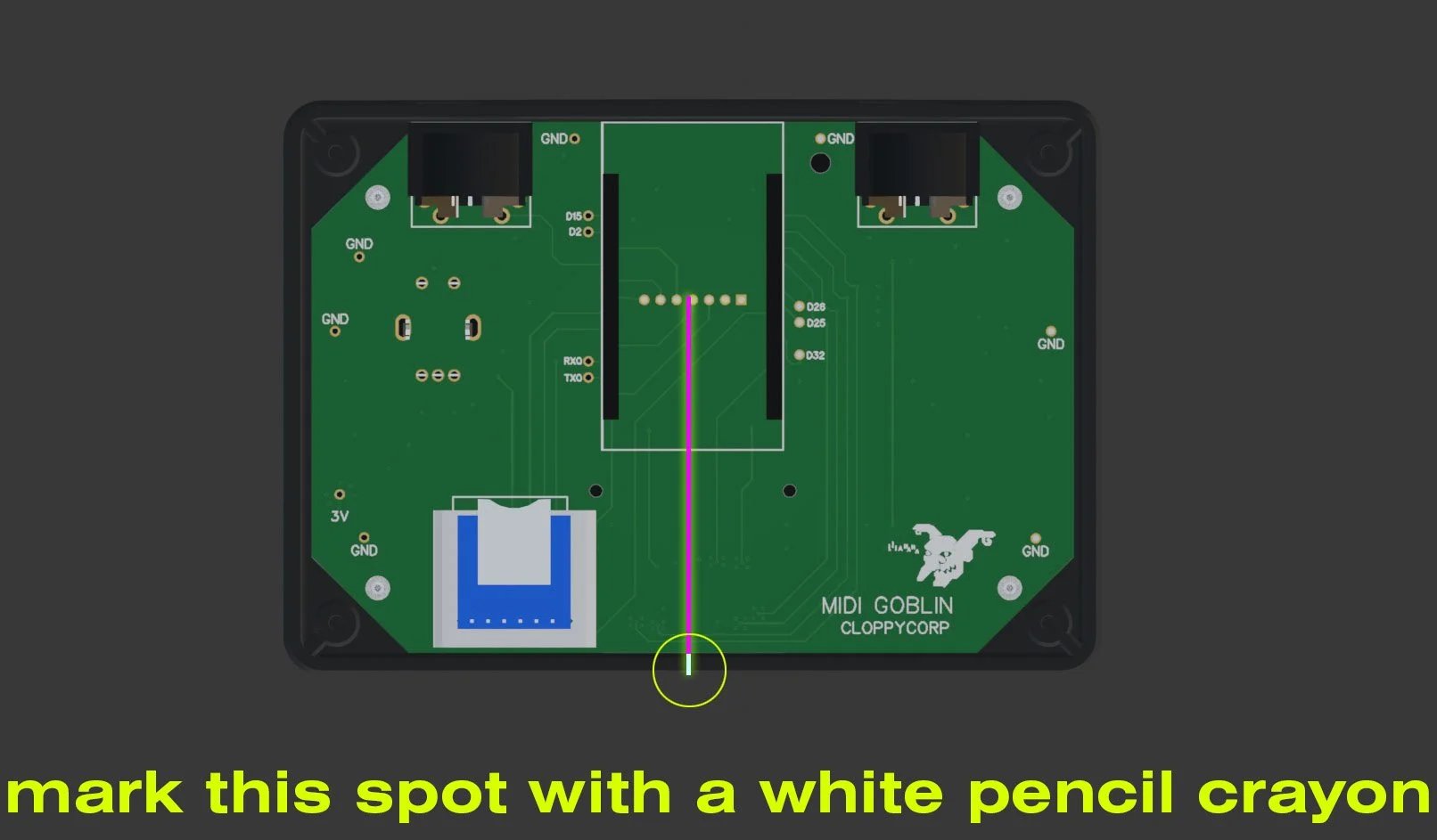
Step 8: measure down from the left side of the center pin to the enclosure lip and mark this spot with a white pencil crayon
Step 9: REMOVE THE ELECTRONICS from the enclosure and from the point you marked on the enclosure lip, measure down 22mm(or 16 mm from the bottom if you’re measuring upwards) - mark this spot with your pencil crayon
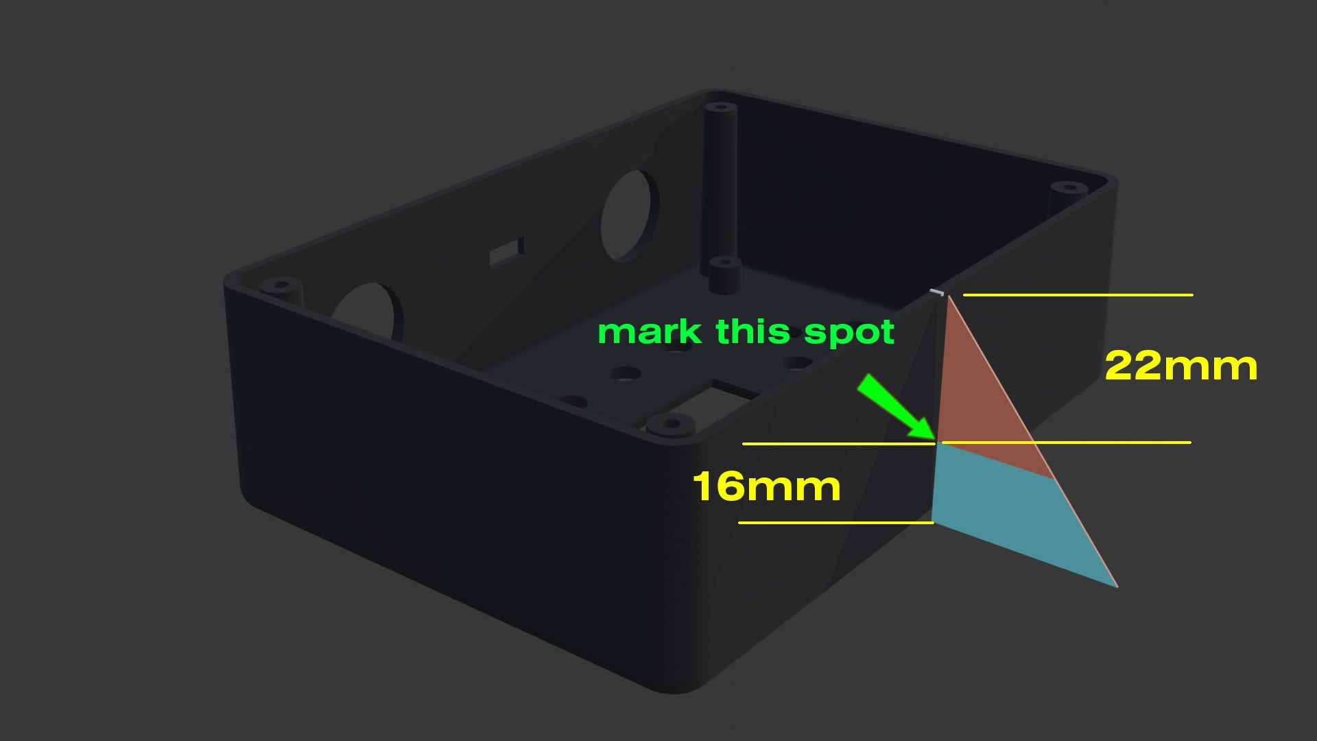
Step 10: with the electronics removed from the enclosure drill a hole at the spot you marked wide enough for the audio jack to fit through (i suggest using a step drill and making the hole a little wider than necessary to accommodate weird audio jacks)
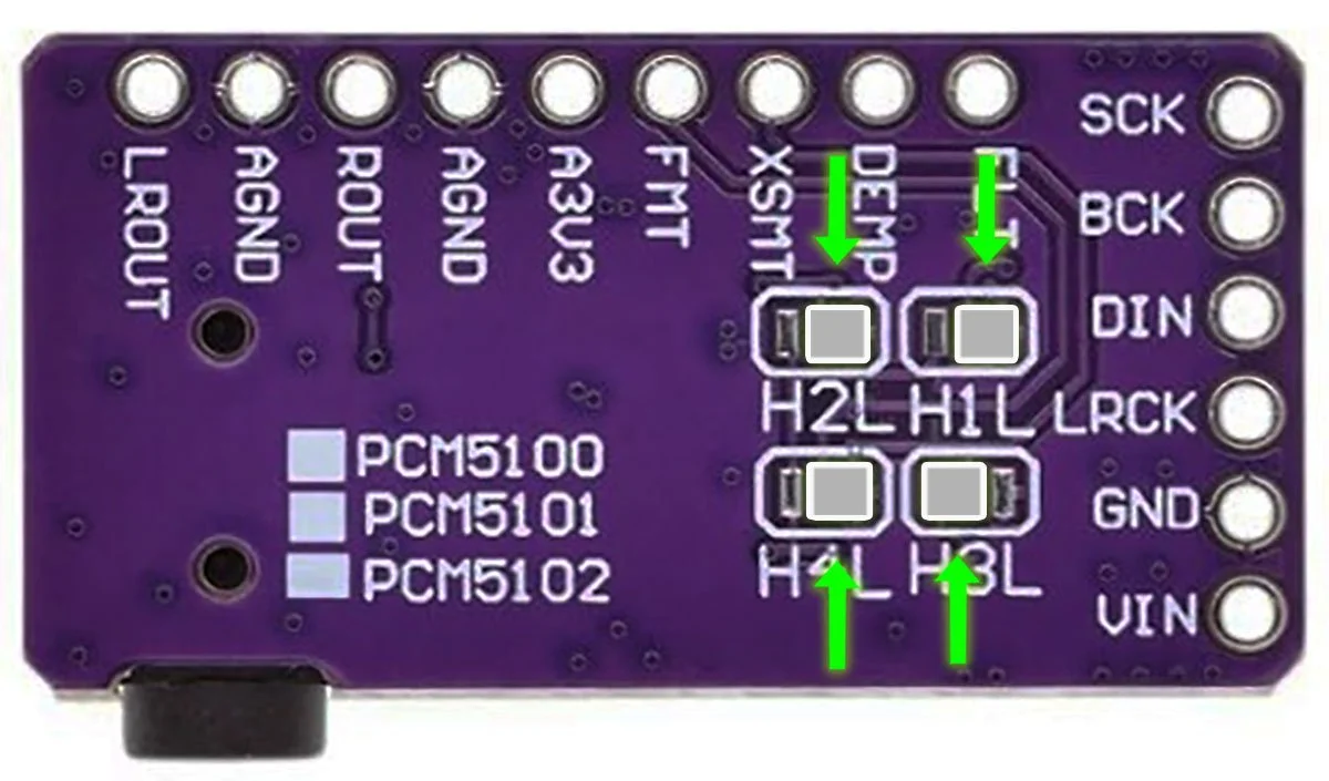
Step 10: bridge the pads on the bottom of the audio module if they did not come pre-bridged (many suppliers sell them un-bridged)
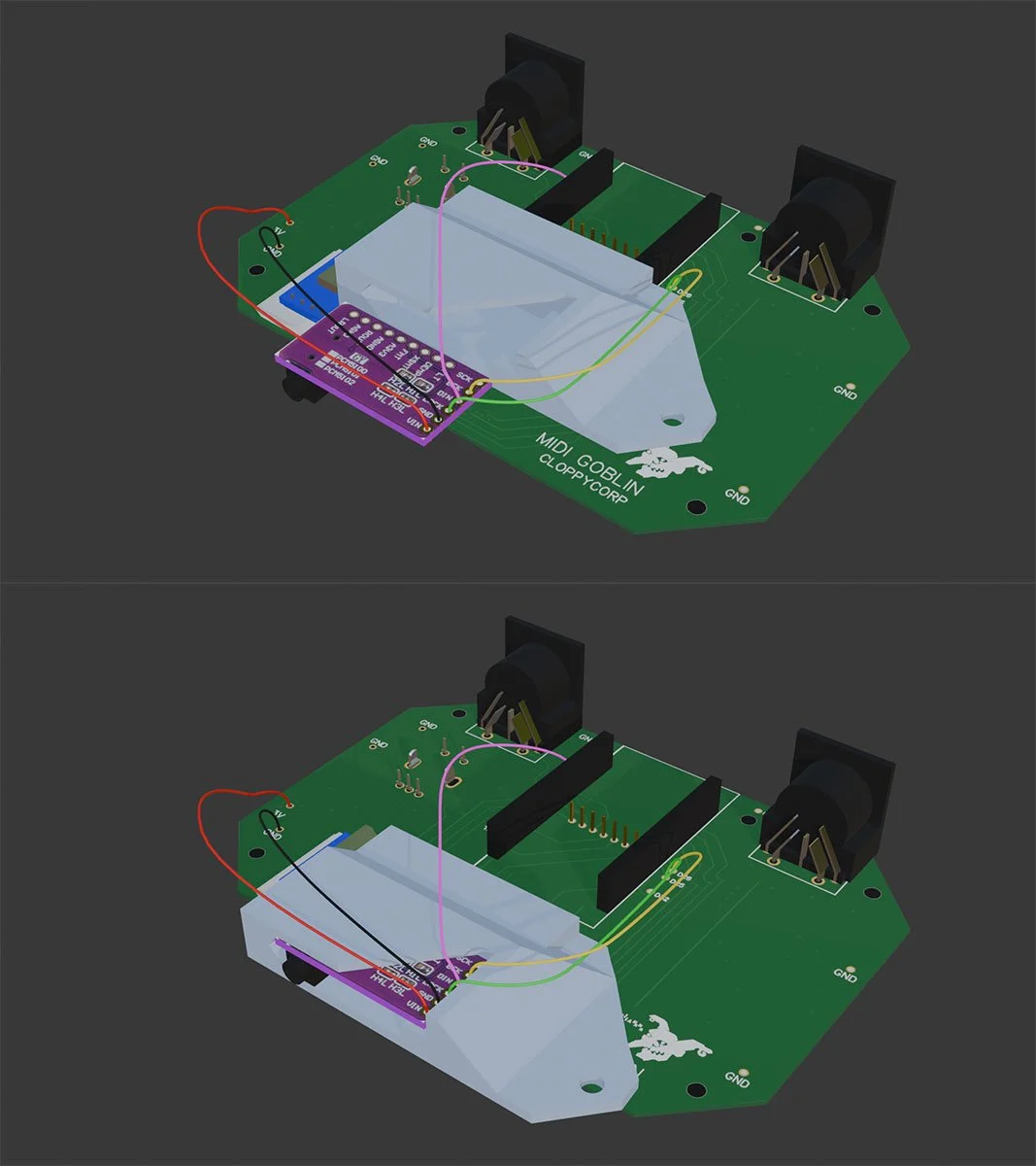
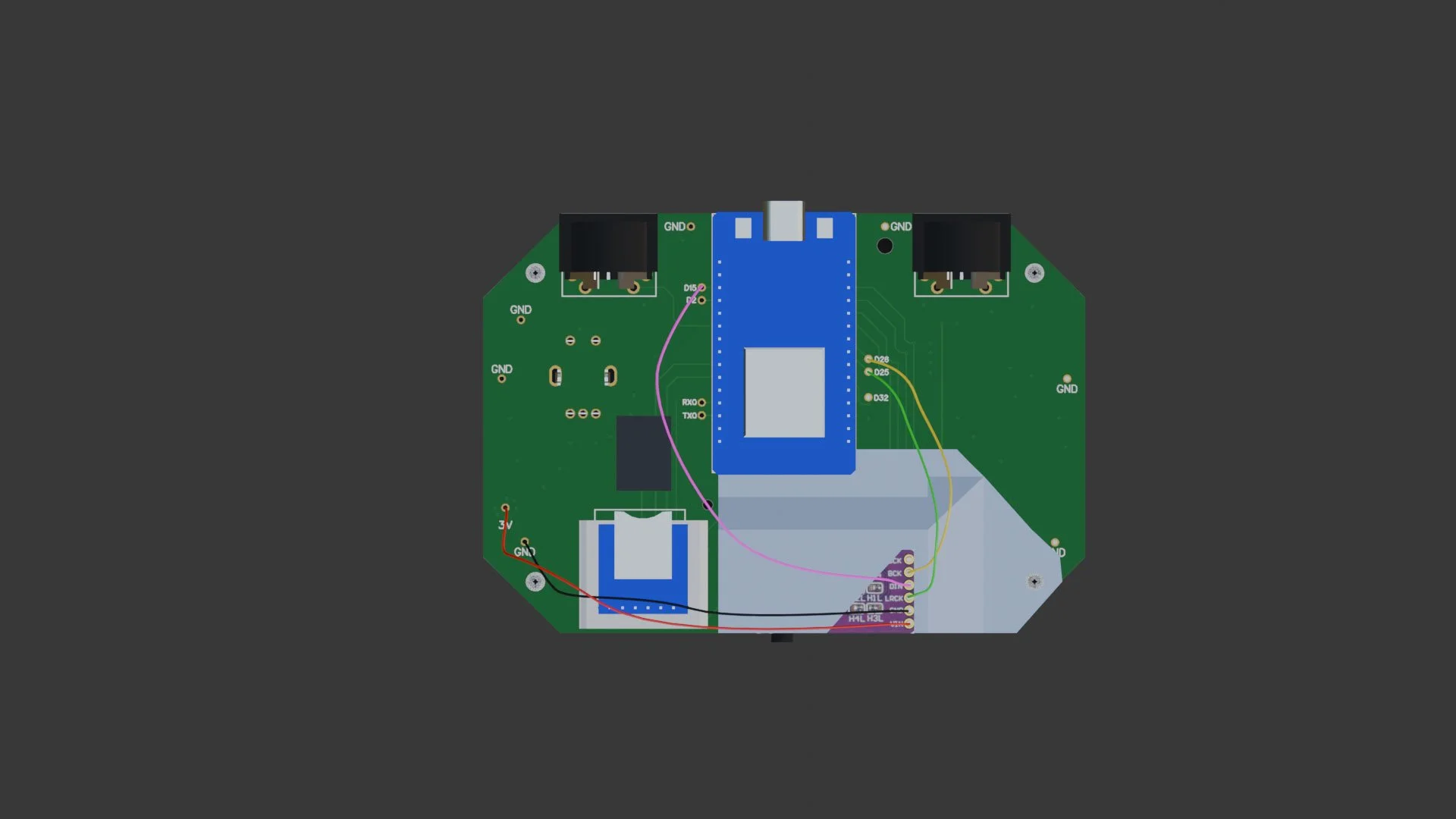
Step 11: solder the audio module to the pcb using different colored wires. The wire lengths should be approximately 5-6 inches (this will give you some slack to work with)
BCK -> D26
DIN -> D15
LRCK -> D25
GND -> GND
VIN -> 3V

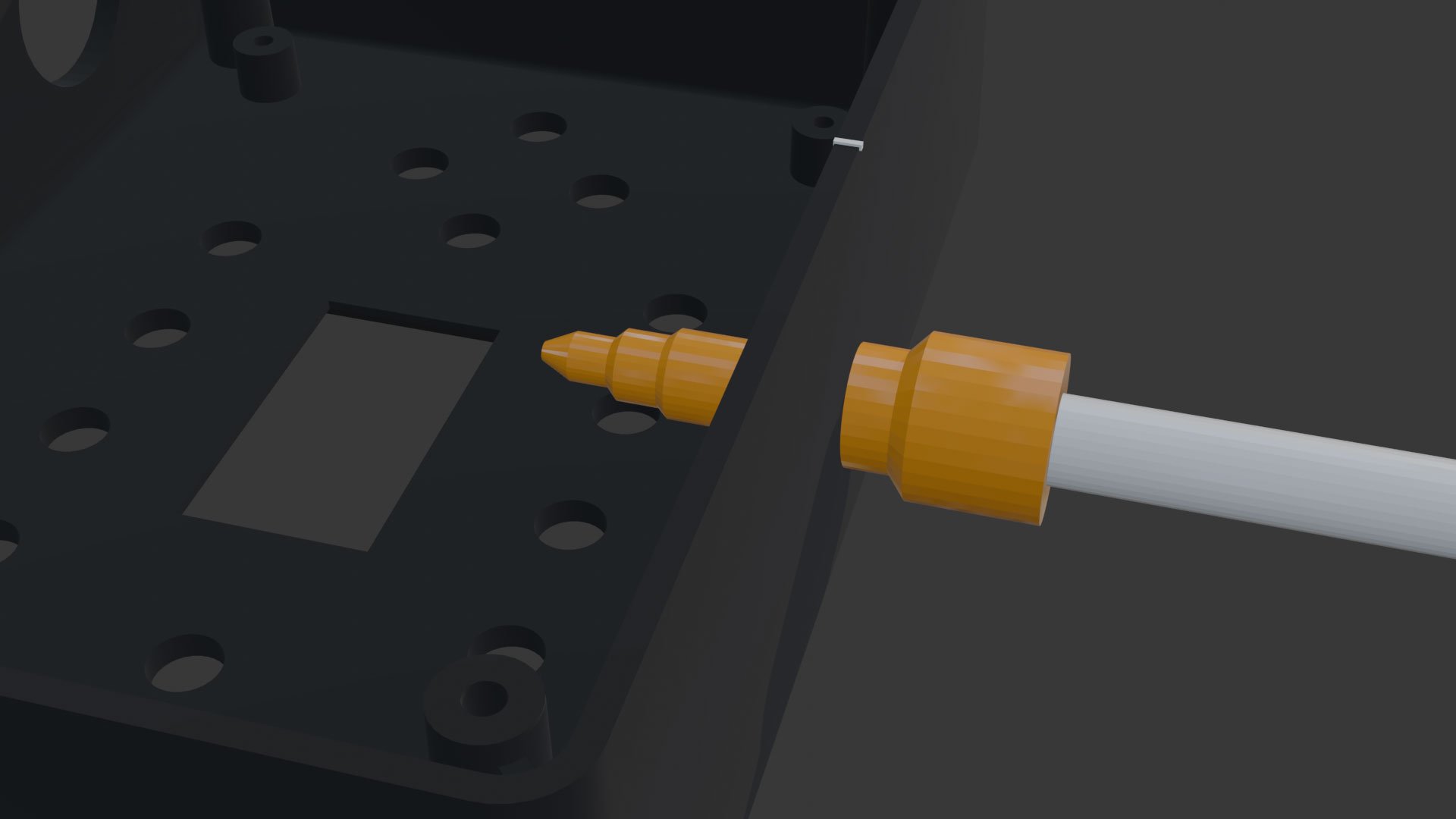
Step 12: Slide the audio module into the 3d printed bracket
Step 13: Re-insert the esp32 into the headers, plop the sd card back into the reader (carefully…) line up the 3d printed bracket like so (the bracket butts up against the headers under the edge of the esp32)
Step 14 - this is kind of tricky but we’re almost done!
put the buttons back into their holes (one hole will be empty for the encoder to fit into)
gently bend the enclosure sides outwards a couple millimeters and insert the electronics back into the enclosure.
You may have to push down a bit to get the esp32’s usb C connector into place (when you do it will make a satisfying “click” sound)
Step 15 - screw the pcb and enclosure lids back in place and put the knob back on the encoder.
Final step: Flash the Goblin with the latest Pingler firmware using the flashing tool.